Leave A Message
If you are interested in our products and want to know more details,please leave a message here,we will reply you as soon as we can.

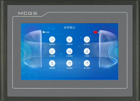
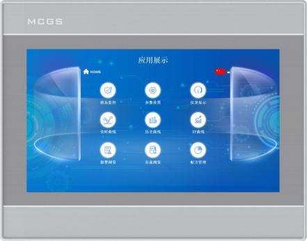
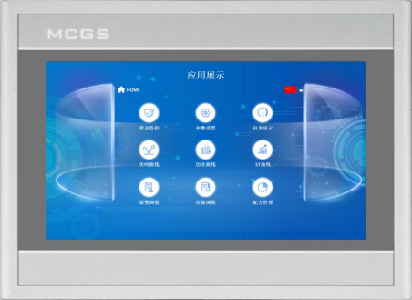
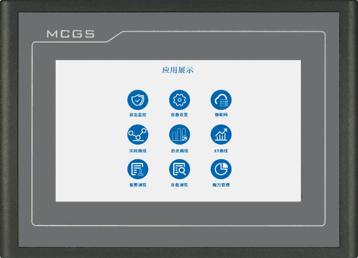
TPC7012Ex is MCGS E‑series embedded industrial HMI without ethernet port, built on RISC‑V C907 multi‑core 800MHz processor. It features 7‑inch TFT 800×480 four‑wire resistive touch display, multiple serial interfaces RS232/RS485/RS422 and mutual‑exclusive USB Host & Slave. Pre‑installed McgsPro configuration software. Front‑panel IP65 protection, CE & FCC certification, industrial EMC level‑2. Powered by 24±20%VDC, ideal for cabinet‑mount machinery and factory automation projects.
Item No :
TPC7012ExOrder(MOQ) :
50Payment :
Paypal\TT\Western UnionProduct Origin :
Guangdong, ChinaWeight :
2KGTPC7012Ex is cost‑effective entry‑level embedded HMI from MCGS Kunlun Jichuang. Adopting RISC‑V C907 multi‑core 800MHz hardware platform, this 7‑inch touch HMI is designed for serial‑communication‑only automation projects, without Ethernet port. Flexible serial ports support connection with PLC, inverter and various field devices. IP65 front‑panel rating offers reliable dust‑proof and splash‑proof performance for cabinet installation scenarios.
Product Specifications
|
Classification |
Item |
TPC7012Ex |
|
Product featu- res |
LCD |
7" TFT |
|
Backlight type |
LED |
|
|
Display color |
65536 |
|
|
Resolution ratio |
800×480 |
|
|
Display Brightn- ess |
250cd/m2 |
|
|
Touch screen |
Four-wire resistive |
|
|
Input voltage |
24±20%VDC |
|
|
Power rating |
7W |
|
|
Processor |
RISC-V C907 – Multi-core, 800 MHz |
|
|
Internal storage |
64MB |
|
|
Flash Memory |
128MB |
|
|
Data storage |
Unlimited |
|
|
Hardware Clock |
Built-in |
|
|
Configuration so- ftware |
McgsPro |
|
|
Peripheral interf- ace |
Serial interface |
Method 1: COM1 (232), COM2 (485), COM3 (485) Method 2: COM1 (232) – COM9 (422) |
|
USB port |
1×Host/1×Slave |
|
|
Ambient condi- tion |
Working temper- ature |
0℃~45℃ |
|
Work environment hum- idity |
5%–90% (no condensation) |
|
|
Storage Temper- ature |
-10℃~60℃ |
|
|
Storage humidity |
5%–90% (no condensation) |
|
|
Size of product |
Chassis material |
Engineering plas- tic |
|
Case color |
Dull grey |
|
|
External dimen- sions |
226mm×163mm |
|
|
Cabinet opening |
215mm×152mm |
|
|
Attestation |
Product certifica- tion |
Complies with CE/FCC certification stan- dards |
|
Levels of protect- ion |
IP65 (Front Panel) |
|
|
Electromagnetic co- mpatibility |
Industrial Level II |
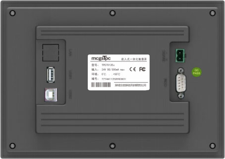
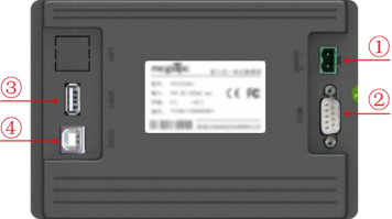
Interface Description
|
① |
Electricity source |
|
|
- |
1 |
0V |
|
+ |
2 |
DC24V |
||||
|
② |
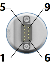
Serial port |
|
COM1 |
2 |
RS232 RXD |
|
|
3 |
RS232 TXD |
|||||
|
5 |
GND |
|||||
|
COM2 |
7 |
RS485+ |
||||
|
8 |
RS485- |
|||||
|
COM3 |
4 |
RS485+ |
||||
|
9 |
RS485- |
|||||
|
COM9 |
7 |
RXD+ |
||||
|
8 |
RXD- |
|||||
|
4 |
TXD+ |
|||||
|
9 |
TXD- |
|||||
|
Note: COM9 cannot be used simultaneously with COM2 or COM3. |
||||||
|
③ |
USB1 Main port |
USB 2.0 supports updating the touchscreen operating environment, engineering files, and the system via a USB flash drive, as well as data import and export functions; this interface operates in parallel with the USB port. |
||||
|
④ |
USB 2.0 Host Port |
USB Type-B port – used for uploading or downloading engineering files; conflicts with the main port. |
||||
Product Installation
l Product Dimensions
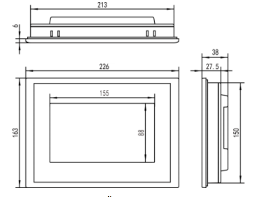
External dimensions
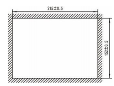
Opening size
l Installation method
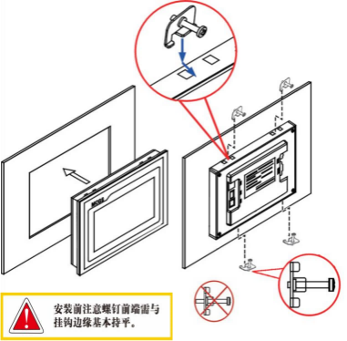
Note before installation: The front end of the screws must be basically flush with the hanger edge.
Hook installation
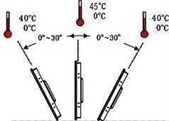
Installation angle
Product Maintenance
Battery Location: On the circuit board inside the TPC product
Battery Specification: CR2032 3V Lithium Battery
Battery Removal: Remove the securing adhesive above the battery, gently pull the positive terminal clip, and the battery will pop out automatically.
Battery Installation: First place the battery into the positive terminal clip, then gently press the other end down until it fits under the plastic clip. Verify that the battery is properly seated in both plastic clips and the metal positive terminal clip.
1.5.1 Replacement battery
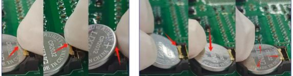
Remove battery Install battery
1.5.2 Touch calibration
Enter TPC In the system settings interface, press and hold on a blank area. 3 The touch calibration process will begin in seconds.
TPC Calibration: Use a stylus or finger to lightly press and hold the center point of the crosshair cursor. When the cursor moves to the next point, lift it.
Repeat this action until the message "New calibration settings have been measured" appears.
Click the "Confirm Calibration" button to save and exit the calibration program.
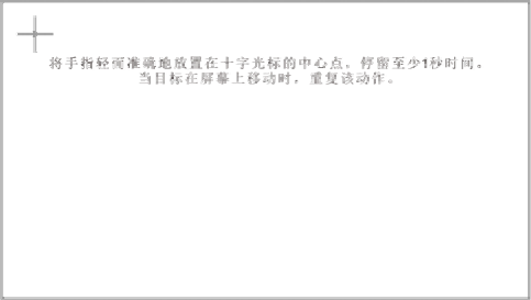
Place your finger lightly and accurately on the center of the crosshair cursor and hold it for at least one second as the target moves across the screen. Repeat this action.
1.5.3 Three-proof film
Applying a triple protection film to the TPC can effectively prevent contamination and corrosion caused by dust, oil stains, and other substances generated during production. Therefore, if necessary, the TPC can be protected with a triple protection film. This section takes the 1271Gn model as an example; the film application steps for other TPC models are similar.
l Preparation Tools: Matched triple protection film for TPC (available through the TPC's purchase channel), dust-free cloth, anti-static environmentally friendly cleaner, and roller.
l Operating steps:
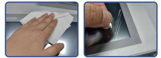
1) Clean the screen. Use a dust cloth to wipe away dirt from the front panel to prevent bubbles when applying the screen protector. If the TPC surface is heavily contaminated, use a cleaning agent to help clean contaminants in the crevices around the edges.
2) Remove the factory-installed PET protective film and clean any residue to prevent bubbles from forming during application.
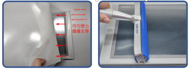
3) Peel off a corner of the backing film on the right side. Align the right side of the film with the right side of the TPC. With your left hand, slowly peel off the backing film, and with your right hand, apply even pressure to gently push the film onto the screen from right to left
4) After applying the film, use a roller to press the adhesive backing firmly to prevent air bubbles.
l Precautions:
1)Before applying the Triple Protection Film, the factory-installed PET protective film must be peeled off.
2)The Triple Protection Film is a consumable. If edge lifting or bubbling is detected, it should be replaced with a new one.
3)When replacing the Triple Protection Film, peel it up from the bottom right corner of the front panel. Be
careful not to scratch the sealed film.
2 Project Download
Step 1: Power on the TPC with a 24V DC power supply. After startup, a progress bar with the message "Press and hold the touch screen to enter the system configuration interface" will appear on the screen. At this point, tap the TPC ① to enter the startup configuration interface; if no action is taken, the device will automatically enter the project runtime interface.
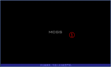
Step 2: Click the System Parameter Settings button ②. Enter TPC System settings interface.
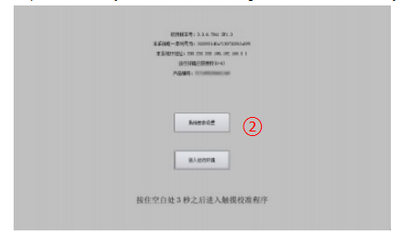
Step 3: Access the TPC System Settings interface – USB – and set the TPC's USB port to "Slave Port" mode. Note: No devices should be connected to the main USB port at this time.

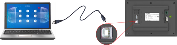
Step 4: Connect the computer to the display's USB port using a USB cable.
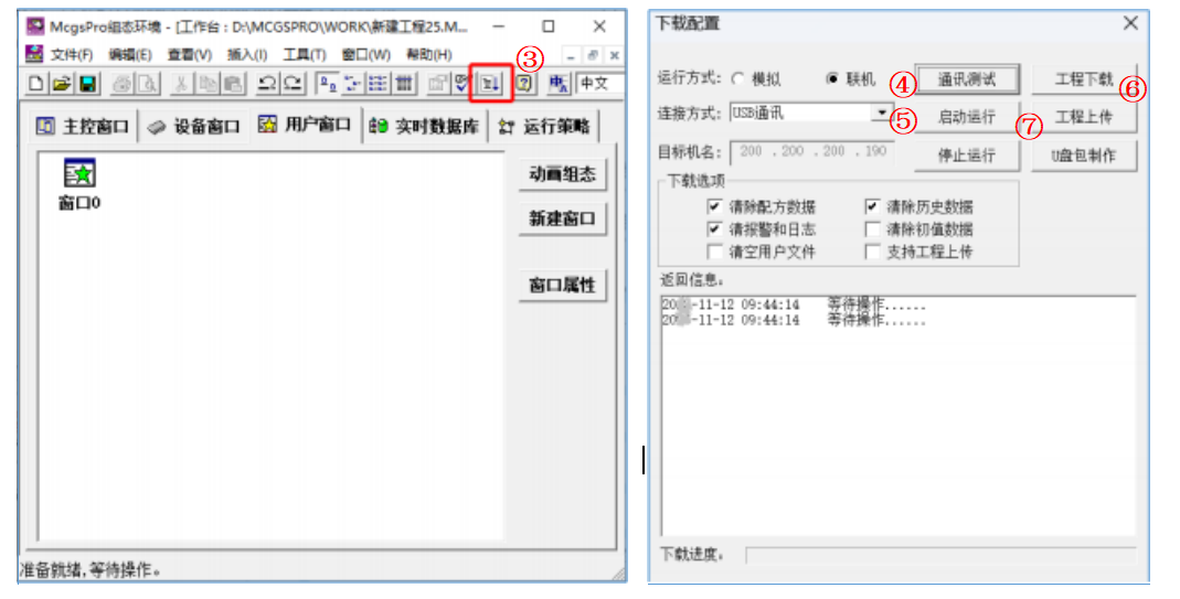
Step 5: Open the TPC project using McgsPro, click "Download Project ③", open the Download Configuration Properties page, select the "Online" runtime mode ④, choose the "USB Communication" connection method ⑤, and click "Download Project ⑥". Once the system confirms that the project download was successful, click "Start Execution ⑦" or the "Enter Runtime Environment" button on the TPC interface to run the screen-based project.

Leave A Message
Scan to Wechat :

Scan to WhatsApp :