Leave A Message
If you are interested in our products and want to know more details,please leave a message here,we will reply you as soon as we can.

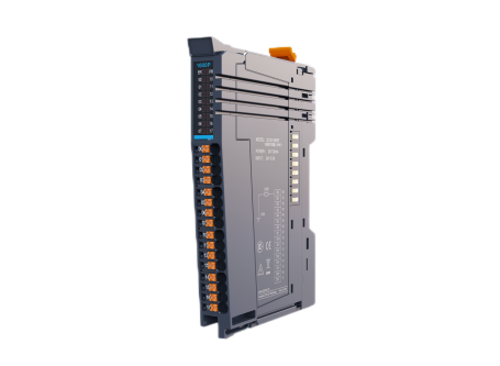
QY20‑2HC is a two‑channel high‑speed pulse input counting module, applicable for ZQ600 series PLC IO expansion and QY20 series coupler IO expansion. It supports 5V differential and 24V single‑ended pulse signal types including AB‑phase, Pulse + Direction, CW/CCW. IP20 protection grade, DIN‑rail backplane bus installation, compact size for cabinet automation control.
Item No :
QY20Order(MOQ) :
20Payment :
Paypal/TT/Western UnionProduct Origin :
Shanghai, ChinaLead Time :
18-30 daysWeight :
5 kgQY20‑2HC is a 2‑channel high‑speed pulse input counting module designed for IO expansion of ZQ600‑series PLC and QY20‑series coupler. Supporting both 5 V differential and 24 V single‑ended pulse signals including AB‑phase, Pulse + Direction and CW/CCW modes, this module is ideal for encoder feedback and motion counting applications. It features IP20 protection grade, compact dimension of 12 × 83 × 100 mm and weight of approx. 60 g, adopting backplane‑buckle installation without hot‑swap support. Powered by DC 5 V from backplane bus with typical current of 85 mA, it provides 0‑30 ms configurable input filtering. Equipped with PR power indicator (red) and ER status/alarm indicator (yellow), the module complies with IEC 61131‑2 Zone B EMC standard and IEC 60068‑2 vibration & shock resistance requirements. Its operating temperature ranges from ‑20 ℃ to 55 ℃, storage temperature from ‑40 ℃ to 70 ℃ with non‑condensing humidity of 10‑90 %RH, and the maximum applicable altitude is ≤2000 m. Please install or detach the module under power‑off status; forced cooling is required if ambient temperature exceeds the rated upper limit.
Product Description
|
Model |
Description |
Machine code |
Applicable model |
|
QY20-2HC |
Two pulse high-speed input counting module |
|
ZQ600 series PLC IO expansion QY20 series coupler IO expansion |
|
Name |
Description |
|||
|
Backplate Buckle |
The pressing state is open and the lifting state is locked |
|||
|
pilot lamp |
PR |
Power on / operation indicator light |
Red |
power light |
|
|
ER |
Incorrect indicator light |
Yellow |
Steady On: The system is running and address allocation is complete. Fast Flashing: Alarm or stop. Slow Flashing: The system is running, but address allocation is not yet complete. |
|
Color coding |
DI: Blue DO: Red AD: Green DA: Orange Others: Purple |
|||
|
Backplane Connection |
Backplane bus and power cable expansion |
|||
|
User Terminal |
User wiring terminal |
|||
Instructions:
Fast flashing: 50ms on, 50ms off.
Slow flashing: 50ms on, 1000ms off.
Technical Specifications
Basic specifications
|
Project |
Specifications |
|
IP grade |
IP20 |
|
Size (width X height X depth) |
12*83*100 |
|
weight |
About 60g |
Power supply specifications
|
Project |
Specifications |
|
Bus input power supply rated voltage |
DC5V |
|
Bus input power supply rated current |
85mA (typical at 5 V) |
|
Module hot plug function |
nonsupport |
Input specification
|
Project |
Specifications |
|
Input type |
Analog Input |
|
Input Channel |
4 channel |
|
Rated voltage |
24V |
|
Input type |
- 5V differential AB phase - 5V differential pulse + direction - 5V differential CW/CCW - 24V single-ended AB phase - 24V single-ended pulse + direction - 24V single-ended CW/CCW |
|
Input filtering |
0~30ms optional |
|
Input Current |
7mA |
|
Input voltage |
5~24V |
Environmental Specifications
|
Project |
Specifications |
|
Operating Environment |
Suitable for environments without corrosive or flammable gases, and where conductive dust is not severe. |
|
Altitude |
≤2000m |
|
Pollution Degree |
Class 2 |
|
Immunity |
Power supply 2kV(IEC 61000‑4‑4) |
|
Overvoltage Category |
I |
|
EMC Immunity Level |
Zone B,IEC61131‑2 |
|
Vibration Resistance |
IEC 60068‑2‑6 5Hz8.4Hz,3.5mm,8.4Hz150Hz,1g,Tested in X/Y/Z axes, 10 cycles per axis |
|
Shock Resistance |
IEC 60068‑2‑27 150m/s2 ,11ms,Tested in ±X/Y/Z directions (6 directions total), 3 times per direction (18 times in total) |
|
Storage Temperature |
Storage Temperature -40°C to 70°C Relative humidity: < 90%RH (non-condensing) |
|
Operating Temperature |
Operating Temperature -20°C to 55°C Relative humidity: 10%RH to 90%RH (non-condensing) Note: When the operating temperature exceeds the maximum limit, a forced fan or air conditioner must be installed in the direction of the cooling vents. |
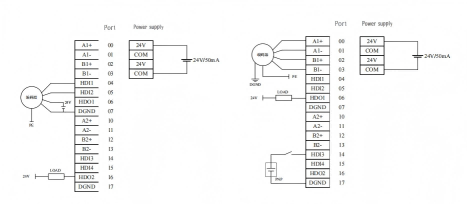
Typical Wiring Diagram
Dimension

Leave A Message
Scan to Wechat :

Scan to WhatsApp :