Leave A Message
If you are interested in our products and want to know more details,please leave a message here,we will reply you as soon as we can.

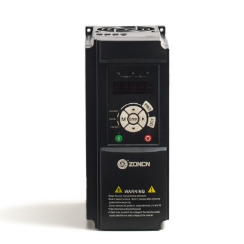
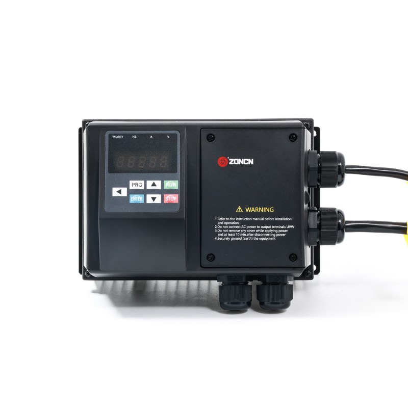
The high-performance AC crane drive system supports various control modes (open-loop and closed-loop), featuring anti-sway, braking, and limit protection functions. It integrates load adaptive control, synchronous control, and rope length detection capabilities, with all models equipped with built-in braking units. The system offers comprehensive fault detection, maintenance alerts, load holding functionality, and hierarchical overload protection, compatible with 380V voltage and power ratings ranging from 3.7 to 690 kW.
Item No :
QZ9000Order(MOQ) :
20Payment :
Paypal/TT/Western UnionProduct Origin :
Shanghai, ChinaColor :
BlackLead Time :
18-30 daysWeight :
80kgThe QZ9000 series system supports both open-loop and closed-loop control modes, featuring VF control, intelligent anti-sway functionality, professional braking logic, and limit sensor integration capabilities, effectively preventing hook travel exceeding limits and overtravel during lifting operations.
The equipment integrates adaptive load acceleration, multi-machine synchronous control, parameter macro-setting, and rope length detection functions, with all models standardly equipped with built-in braking units. It also features torque monitoring, automatic motor parameter adjustment, braking fault self-diagnosis, operation and maintenance alerts, and load holding capabilities. The system offers tiered overload protection: stable operation at 110% rated load, continuous operation at 150% load for 60 seconds, and short-term operation at 180% load for 3 seconds.
Product Features
Technical Specifications
| Item | QZ9000 Specification | |
|
Control Mode |
V/F control Sensorless flux vector control (SVC) Close-loop vector control (FVC) |
|
|
Maximum frequency |
0~150Hz |
|
|
Carrier frequency |
1kHz~12kHz The carrier frequency is automatically adjusted based on the load features. |
|
|
Input frequency resolution |
Digital setting:0.01Hz Analog setting: Maximum frequency x 0.025% |
|
|
Start torque |
G type:0.25Hz/150%(SVC); 0Hz/180% (FVC) |
|
|
Speed range |
1:200 (SVC) |
1:1000 (FVC) |
|
Speed stability accuracy |
±0.5% (SVC) |
±0.02% (FVC) |
|
Torque control accuracy |
±5% (SVC),±3% (FVC) |
|
|
Overload capacity |
G Type:60s for 150% of the rated current, 3s for 180% of the rated current. |
|
|
Torque boost |
Auto-boost; Customized boost: 0.1%~30.0% |
|
|
Ramp Mode |
Straight-line or curve ramp. Three groups of acceleration/deceleration time with the range of 0.00`6500.0s |
|
|
Multiple speeds |
It implements up to 8 speeds via terminal states |
|
|
Auto voltage regulation (AVR) |
It can keep constant output voltage automatically when the mains voltage changes |
|
|
Over-voltage/over-current stall control |
The current and voltage are limited automatically during the running process so as to avoid frequent tripping due to over voltage/over current |
|
|
Rapid current limit |
It helps to avoid frequent over current faults of the inverter. |
|
|
Torque limit and control |
It can limit the torque automatically and prevent frequent over current tripping during the running process. Torque control can be implemented in the FVC mode. |
|
|
Support for kinds of PG cards |
Support for PG cards of resolver, differential, open collector |
|
|
Instantaneous stop doesn’t stop |
The load feedback energy compensates the voltage reduction so that the inverter can continue to run for a short time. |
|
|
Communication |
RS-485,CAN |
|
|
Protection mode |
Motor short-circuit detection at power-on, input/output phase loss protection, over current protection, over voltage protection, under voltage protection, overheat protection and overload protection |
|
|
Lifting process control |
Inverter built in anti-sway, grab and other complex lifting process control, used for lifting, translation, slewing and other driving in lifting equipment. |
|
|
Input terminal |
Maximum 10 digital input terminals 2 analog input terminals 1 voltage input (only support for 0~10V,),1 voltage input(0~10V) or current input (4~20mA) (Different power are with different terminals, see details at circuit description) |
|
|
Frequency source |
Digital setting, analog voltage setting, analog current setting, communication setting, serial port setting. You can perform switchover in various ways. |
|
|
Command source |
Operation panel/Control terminals/Serial communication port You can perform switchover between these sources in various ways. |
|
|
Output terminal |
2 digital output terminals 2 relay output terminals |
|
|
LED display |
It display the parameter |
|
|
Key locking and function selection |
It can lock the keys partially or completely and define the function range of some keys so as to prevent mal-function. |
|
|
Installation location |
Indoor, free from direct sunlight, dust, corrosive gas, combustible gas, oil smoke, vapor, drip or salt. |
|
|
Altitude |
Lower than 1000m |
|
|
Ambient temperature |
-10℃~+40℃(de-rated if the ambient temperature is between 40℃~50℃) |
|
|
Humidity |
Less than 95%RH,without condensing |
|
|
Vibration |
Less than 5.9m/s2(0.6g) |
|
|
Storage temperature |
-20℃~+60℃ |
|
Specifications
Voltage:3PH AC380V±15%
|
Model No. |
Input voltage | Rated output power(KW) |
Rated input current(A) |
Rated output current(A) |
Motor Power (KW) |
|
QZ9400-7R5G |
3PH AC380V±15% |
7.5 |
20.0 |
17.0 |
7.5 |
|
QZ9400-11G |
11 |
26.0 |
25.0 |
11 |
|
|
QZ9400-15G |
15 |
35.0 |
32.0 |
15 |
|
|
QZ9400-18.5G |
18.5 |
38.0 |
37.0 |
18.5 |
|
|
QZ9400-22G |
22 |
46.0 |
45.0 |
22 |
|
|
QZ9400-30G |
30 |
62.0 |
60.0 |
30 |
|
|
QZ9400-37G |
37 |
76.0 |
75.0 |
37 |
|
|
QZ9400-45G/ |
45 |
92.0 |
90.0 |
45 |
|
|
QZ9400-55G |
55 |
113.0 |
110.0 |
55 |
|
|
QZ9400-75G |
75 |
157.0 |
150.0 |
75 |
|
|
QZ9400-90G |
90 |
180.0 |
176.0 |
90 |
|
|
QZ9400-110G |
110 |
214.0 |
210.0 |
110 |
|
|
QZ9400-132G |
132 |
256.0 |
253.0 |
132 |
|
|
QZ9400-160G |
160 |
307.0 |
300.0 |
160 |
|
|
QZ9400-200G |
200 |
385.0 |
380.0 |
200 |
|
|
QZ9400-220G |
220 |
430.0 |
420.0 |
220 |
|
|
QZ9400-250G |
250 |
475.0 |
470.0 |
250 |
|
|
QZ9400-280G |
280 |
525.0 |
520.0 |
280 |
|
|
QZ9400-315G |
315 |
610.0 |
600.0 |
315 |
|
|
QZ9400-350G |
350 |
665.0 |
640.0 |
350 |
|
|
QZ9400-400G |
400 |
700.0 |
690.0 |
400 |
|
|
QZ9400-450G |
450 |
800.0 |
790.0 |
450 |
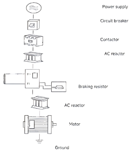
Typical Wiring Diagram
Dimension
TYPE B
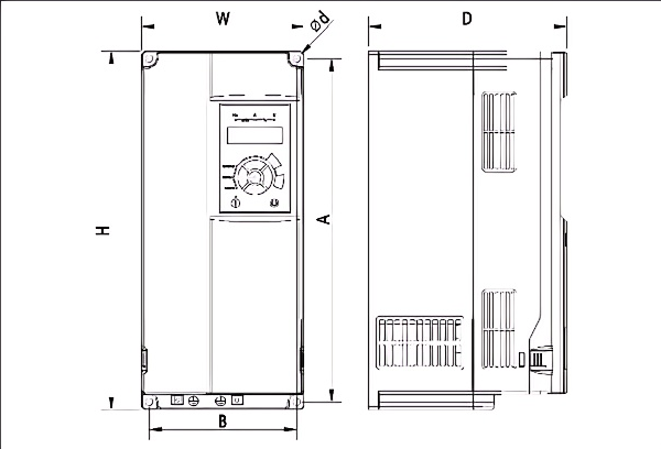
|
Type |
Inverter model |
W |
H |
D |
A |
B |
Ød |
|
B |
QZ9400-7R5G QZ9400-11G |
106 |
240 |
168 |
230 |
96 |
4.5 |
|
B |
QZ9400-15G QZ9400-18.5G QZ9400-22G |
151 |
332 |
183 |
318 |
137 |
7 |
|
B |
QZ9400-30G QZ9400-37G |
217 |
400 |
216 |
385 |
202 |
7 |
TYPE C
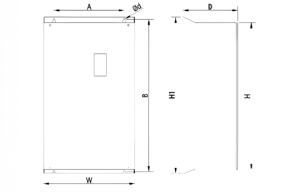
|
Type |
Inverter model |
W |
H |
H1 |
D |
A |
B |
Ød |
|
C |
QZ9400-45G QZ9400-55G |
300 |
440 |
470 |
240 |
200 |
455 |
9 |
|
C |
QZ9400-75G QZ9400-90G QZ9400-110G |
275 |
590 |
630 |
310 |
200 |
612 |
9 |
|
C |
QZ9400-132G QZ9400-160G |
400 |
675 |
715 |
310 |
320 |
695 |
11 |

Leave A Message
Scan to Wechat :

Scan to WhatsApp :