Leave A Message
If you are interested in our products and want to know more details,please leave a message here,we will reply you as soon as we can.

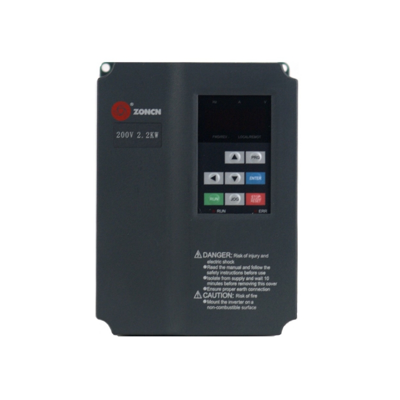
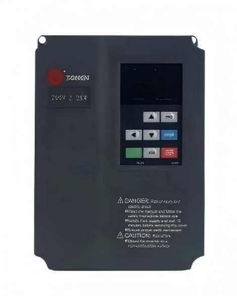
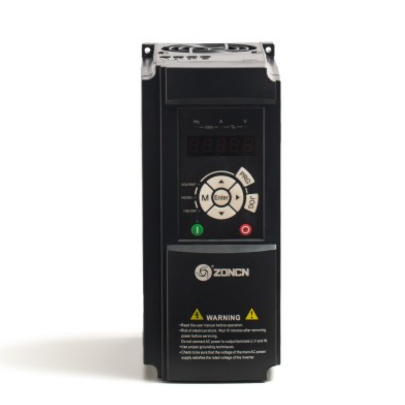
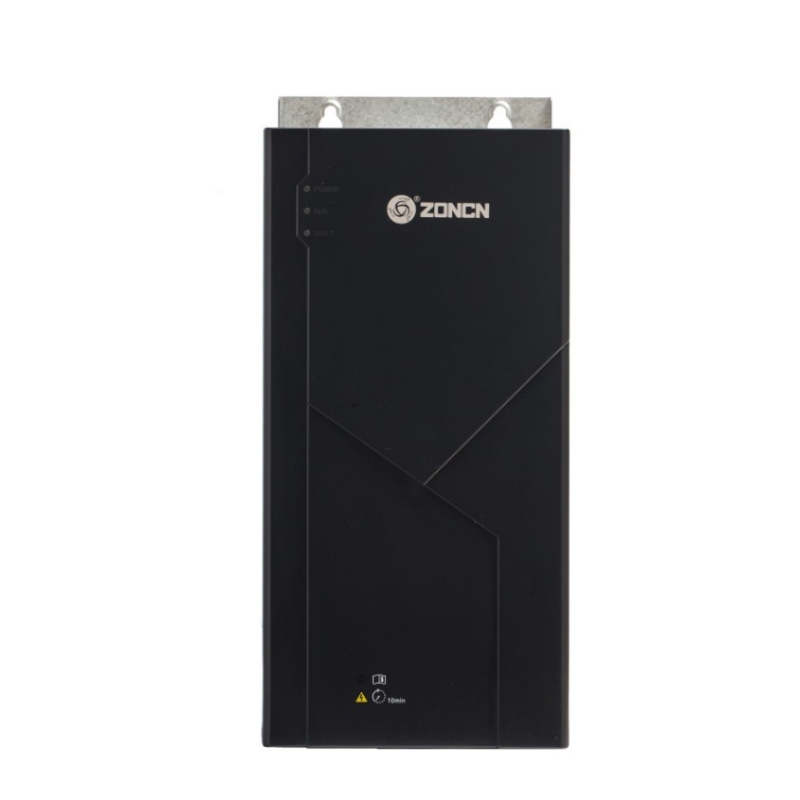
Z8000 series uses variable frequency and on-board PID control, features Modbus communication, and automatically adjusts frequency to suit diverse industrial applications.
Item No :
Z8000Order(MOQ) :
20Payment :
Paypal/TT/Western UnionProduct Origin :
Shanghai, ChinaColor :
BlackLead Time :
18-30 daysWeight :
3 kgThe system uses frequency conversion control and onboard PID control, with optional Modbus communication. It automatically adjusts frequency according to load characteristics, offering a broad frequency range suitable for most applications and compatibility with various PG cards. Tailored for industrial settings, it includes tension control and spindle servo features, along with support for permanent magnet motors.
Product Features
The carrier frequency is automatically adjusted based on the load features
Wide Frequency range, adapt to most applications
V/F control, On board PID control; Modbus communication (Optional parts)
Support for various PG card; Special for kinds of industries, with tension control, spindle servo, support for PM motor ect
Power range.220V 0.4kW~3.7kW380V 0.75kW~1000kW690V 11kW~1400kW
Technical Specifications
| Item | Z8000 Specification | |
|
Control mode |
Sensorless flux vector control (SFVC) Closed-loop vector control (CLVC) Voltage/Frequency (V/F) control |
|
|
Maximum frequency |
Vector control: 0–320 Hz V/F control: 0–3200Hz |
|
|
Carrier frequency |
1–16 kHz The carrier frequency is automatically adjusted based on the load features. |
|
|
Input frequency e solution |
Dgital setting: 0.01 HZ Analog setting: maximum frequency x 0.025% |
|
|
startup torque |
G type: 0.5HZ/150% (SF VC);0HZ/180% (CL VC) p type: 0.5HZ/100% |
|
|
speed range |
1:100 (SF VC) |
1:1000 (CL VC) |
|
speed stability accuracy |
±0.5% (SF VC) |
0.02% (CL VC) |
|
Torque control accuracy |
± 5% (CL VC) |
|
|
Overload capacity |
G type: 60s for 150%of the rated current, 3s for 180%of the rated current. p type: 60s for 120% of the rated current,3s for 150%of the rated current. |
|
|
Torque boost |
Fixed boost customized boost 0.1%-30.0% |
|
|
V/F curve |
straight-line VIF curve Multi-point VIF curve N-power VIF curve (1.2-power ,1.4-power, 1.6-power, 1.8-power, square) |
|
|
VIF separation |
Two types: complete separation; half separation |
|
|
Ramp mode |
straight-line ramp S-curve ramp Four groups of acceleration/deceleration time with the range of0.0-6500.0s |
|
|
Dc braking |
Dc braking frequency:0.00 Hz to maximum frequency Braking time: 0.0-100.0s Braking action current value: 0.0%-100.0% |
|
|
JOG Control |
JOG frequency range:0.00-50.00 HZ JOG acceleration/deceleration time: 0.0- 6500.0s |
|
|
onboard multiple preset speeds |
It implement s up to 16speeds via the simple PLC function or combination of x terminal states |
|
|
onboard PID |
It realizes process-controlled closed loop control system easily |
|
|
Auto voltage regulation (AVR) |
It can keep constant output voltage automatically when the mains voltage changes. |
|
|
over voltage l over current s tall control |
The current and voltage are limited automatically during the running process so as to avoid frequent tripping due to over voltage l over current. |
|
|
Torque limit and control |
It can limit the torque automatically and prevent frequent over current tripping during the running process. Torque control can be implemented in the CLVC mode. |
|
|
support for multiple PG card |
Support for rotating transformer PG card, differential input PG card, UVW differential input PG card, resolve r PG cardan doc input PG card |
|
|
power dip ride through |
The load feedback energy compensate s the voltage reduction so that the Ac drive can continue to run for a short time. |
|
|
Rapid current limit |
It helps to avoid frequent over current faults of the AC drive. |
|
|
High performance |
control of asynchronous motor and synchronous motor are implemented through the high- performance current vector control technology. |
|
|
Timing control |
Time range:0.0-6500.0 minutes |
|
|
communication methods |
Mod bus(standard), pro fi bus-DP(optional), CAN link(optional), CAN(optional) |
|
|
protection mode |
Motor short-circuit detection at power-on, input l output phase loss protection, over current protection, over voltage protection, under voltage protection, overheat protection and over load protection. |
|
|
Input terminal |
8 digital input terminals, one of which supports up to 100 KHZ high-speed pulse input. 2 analog input terminals, one of which only supports 0-10 v voltage input and the other supports 0-10 v voltage input or4-20 mA current input |
|
|
Frequency source |
Digital setting, analog voltage setting, analog current setting, pulse setting and serial communication port setting. |
|
|
Auxiliary frequency source |
There are ten auxiliary frequency sources. It can implement fine tuning of auxiliary frequency and frequency synthesis. |
|
|
Running command source |
operation panel/control terminals/serial communication port you can perform switch over between these sources in various ways. |
|
|
output termina |
1 high-speed pulse output terminal (open- collector)that supports 0-100 KHZ square wave signal output 1 digital output terminal 2 relay output terminal 2 analog output terminal : that supports 0-20 mA current output oro-10 voltage output |
|
|
LED display |
It displays the parameters. |
|
|
key locking and function s election |
It can lock the keys partially or completely and define the function range of some keys so as to prevent mis-function. |
|
|
optional parts |
Rotating transformer PG card, differential input PG card, UVW differential input PG card, resolve r PG card and oc input PG card |
|
|
Installation location |
Indoor, free from direct sunlight, dust, corrosive gas, combustible gas, oi l smoke , vapour , drip or salt. |
|
|
Altitude |
Lower than 1000 m |
|
|
Ambient temperature |
-10"c~40c (de-rated if the ambient temperature is between40c and50c) |
|
|
Humidity |
Less than 95%RH, without condensing |
|
|
vibration |
Less than 5.9 m/s2 (0.6g) |
|
|
storage temperature |
-20'C~60'C |
|
Specifications
| Model | Rated Output Power (KW) | Rated Input Current (A) | Rated Output Current (A) | Motor Power(KW) |
| 1PH/3PH AC 220V -15%~15% | ||||
|
Z8200-0R4G |
0.4 |
5.4 |
2.4 |
0.4 |
|
Z8200-0R7G |
0.75 |
7.2 |
4.5 |
0.75 |
|
Z8200-1R5G |
1 .5 |
10 |
7.0 |
1 .5 |
|
Z8200-2R2G |
2.2 |
16 |
10.0 |
2.2 |
|
Z8200-3R7G |
3.7 |
23 |
16.0 |
3.7 |
|
3PH AC380V±15% |
||||
|
Z8400-0R4G |
0.4 |
3.4 |
1 .2 |
0.4 |
|
Z8400-0R7G |
0.75 |
3.8 |
2.5 |
0.75 |
|
Z8400-1R5G |
1 .5 |
5 |
3.7 |
1 .5 |
|
Z8400-2R2G |
2.2 |
5.8 |
5.0 |
2.2 |
|
Z8400-3R7G/5R5P |
3.7/5.5 |
10.0/15.0 |
9.0/13.0 |
3.7/5.5 |
|
Z8400-5R5G/7R5P |
5.5/7.5 |
15.0/20.0 |
13.0/1 7.0 |
5.5/7.5 |
|
Z8400-7R5G/11 P |
7.5/11 |
20.0/26.0 |
17.0/25.0 |
7.5/11 |
|
Z8400-11G/15P |
11/15 |
26.0/35.0 |
25.0/32.0 |
11/15 |
|
Z8400-15G/18.5P |
15/18.5 |
35.0/38.0 |
32.0/37.0 |
15/18.5 |
|
Z8400-18.5G/22P |
18.5/22 |
38.0/46.0 |
37.0/45.0 |
18.5/22 |
|
Z8400-22G/30P |
22/30 |
46.0/62.0 |
45.0/60.0 |
22/30 |
|
Z8400-30G/37P |
30/37 |
62.0/76.0 |
60.0/75.0 |
30/37 |
|
Z8400-37G/45P |
37/45 |
76.0/90.0 |
75.0/90.0 |
37/45 |
|
Z8400-45G/55P |
45/55 |
90.0/105.0 |
90.0/110.0 |
45/55 |
|
Z8400-55G |
55 |
105.0 |
110.0 |
55 |
|
Z8400-75P |
75 |
140.0 |
1 50.0 |
75 |
|
Z8400-75G/90P |
75/90 |
140.0/160.0 |
150.0/176.0 |
75/90 |
|
Z8400-90G/110P |
90/110 |
160.0/210.0 |
176.0/210.0 |
90/110 |
|
Z8400-110G/132P |
110/132 |
210.0/240.0 |
210.0/253.0 |
110/132 |
|
Z8400-132G/160P |
132/160 |
240.0/290.0 |
253.0/300.0 |
132/160 |
|
Z8400-160G/185P |
160/185 |
290.0/330.0 |
300.0/340.0 |
160/185 |
|
Z8400-185G/200P |
185/200 |
330.0/370.0 |
340.0/380.0 |
185/200 |
|
Z8400-200G/220P |
200/220 |
370.0/410.0 |
380.0/420.0 |
200/220 |
|
Z8400-220G/250P |
220/250 |
410.0/460.0 |
420.0/470.0 |
220/250 |
|
Z8400-250G/280P |
250/280 |
460.0/500.0 |
470.0/520.0 |
250/280 |
|
Z8400-280G/315P |
280/315 |
500.0/580.0 |
520.0/600.0 |
280/315 |
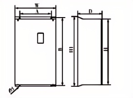
Dimension
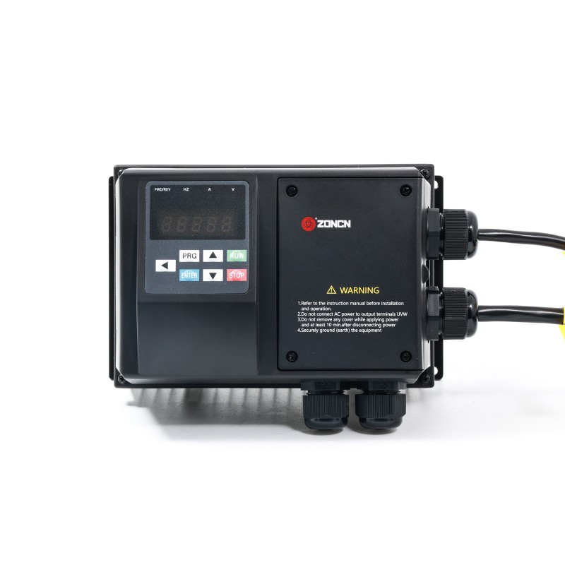
(1)Wall-mounted
(2)Cabinet Installation
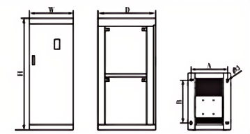
Model |
Outline Dimension(mm) | Installation Size(mm) | Unit: mm | ||
|---|---|---|---|---|---|
| D | A*B*Φd | Installation | Remark | ||
|
Z8200- OR4G |
140
|
117*160*Φ5
|
wall- mounted |
all plastic
|
|
|
Z8200- OR7G |
|||||
|
Z8200- 1R5G |
|||||
|
Z8200- 2R2G |
|||||
|
Z8200- 3R7G |
143 |
105*208*Φ5 |
semi plastic |
||
|
Z8400- OR4G |
140 |
117*160* Φ5
|
all plastic |
||
|
Z8400- OR7G |
|||||
|
Z8400- 1R5G |
|||||
|
Z8400- 2R2G |
|||||
|
Z8400-3R7G/5R5P |
143 |
105*208*Φ5 |
semi plastic |
||
|
Z8400-5R5G/7R5P |
170 |
168*248*Φ6.5 |
all plastic |
||
|
Z8400-7R5G/11 P |
|||||
|
Z8400-11G/15P |
190 |
195*310*Φ6.5 |
semi plastic
|
||
|
Z8400-15G/18.5P |
|||||
|
Z8400-18.5G/22P |
189 |
262*390*Φ6.5 |
|||
|
Z8400-22G/30P |
|||||
|
Z8400-30G/37P |
|||||
|
Z8400-37G-NN |
|||||
|
Z8400-37G/45P |
212 |
200*433*Φ9 |
iron shell
|
||
|
Z8400-45G/55P |
236 |
200*538*Φ9 |
|||
|
Z8400-55G |
|||||
|
Z8400-75P |
|||||
|
Z8400-75G/90P |
256.5 |
270*560*Φ9 |
iron shell (new Product)
|
||
|
Z8400-90G/110P |
300 |
270*564*Φ9 |
|||
|
Z8400-110G/132P |
|||||
|
Z8400-132G/160P |
330 |
wall- mounted 300*765*Φ11or cabinet 250*350*Φ12
|
wall-mounted or cabinet
|
iron shell | |
|
Z8400-160G/185P |
|||||
|
Z8400-185G/200P |
335 |
wall-mounted 400*835*Φ11or cabinet 250*450*Φ12
|
|||
|
Z8400-200G/220P |
|||||
|
Z8400-220G/250P |
|||||
|
Z8400-250G/280P |
350 |
wall-mounted 600*915*Φ11or cabinet 250*620*Φ12 |
|||
|
Z8400-280G/315P |
|||||
|
Z8400-315G/350P |
|||||
|
Z8400-350G/400P |
800 |
550*700*Φ13
|
cabinet |
||
|
Z8400-400G/450P |
|||||
|
Z8400-450G/500P |
|||||
|
Z8400-500G/560P |
800 |
600*700*Φ13
|
|||
|
Z8400-560G/630P |
|||||
|
Z8400-630G/710P |
|||||
|
Z8400-710G/800P |
1000 |
650*900*Φ13 |
|||
|
Z8400-800G/900P |
|||||
|
Z8400-900G/1000P |
|||||
|
Z8400- 1000G |
|||||

Leave A Message
Scan to Wechat :

Scan to WhatsApp :